Friday 29 March 2013


Connecting Two Computers With Cable Through Central Infrastructure

Rather than cable two computers directly, the computers may instead be joined indirectly through a central network fixture. This method requires two network cables, one connecting each computer to the fixture. Several types of fixtures exist for home networking:

  • Ethernet hubs, switches, and routers
  • USB hubs
  • Phoneline and powerline wall outlets

Implementing this method often entails additional up-front cost to purchase more cables and network infrastructure. However, it's a general-purpose solution accommodating any reasonable number of devices (e.g, ten or more). You will likely prefer this approach if you intend to expand your network in the future.

Most cabled networks utilize Ethernet technology. Alternatively, USB hubs can be employed, while powerline and phoneline home networks each offer their own unique form of central infrastructure. The traditional Ethernet solutions are generally very reliable and offer high performance.

Connecting Two Computers Wirelessly


In recent years, wireless solutions have enjoyed increasing popularity for home networking. As with cabled solutions, several different wireless technologies exist to support basic two computer networks:

  • Wi-Fi
  • Bluetooth
  • infrared

Wi-Fi connections can reach a greater distance than the wireless alternatives listed above. Many newer computers, especially laptops, now contain built-in Wi-Fi capability, making it the preferred choice in most situations. Wi-Fi can be used either with or without a network fixture. With two computers, Wi-Fi networking minus a fixture (also called ad-hoc mode) is especially simple to set up.

How To - Set Up an Ad Hoc WiFi Network

Follow these step-by-step instructions to set up an ad hoc Wi-Fi network. A Wi-Fi network in ad hoc (also known as computer-to-computer or peer) mode allows two or more devices to communicate with each other directly instead of through a central wireless router or access point.

Difficulty: Average
Time Required: less than 30 minutes
Here's How:


  • For each of the computers (devices) to be connected via ad hoc networking, determine whether they have Wi-Fi capability. Purchase and install Wi-Fi network adapter hardware if needed.
  • Decide on a name and a Wi-Fi security password for the ad hoc network to be created.
  • To set up an ad hoc Wi-Fi connection in Microsoft Windows, first choose the "Set up a new connection or network" option in Network and Sharing Center, then choose the "Set up a wireless ad hoc (computer-to-computer) network" option and click Next to start the process. Follow the instructions provided with each step.
  • To set up ad hoc Wi-Fi from Mac OS X, choose the "Create Network..." menu option from AirPort (usually accessible from the main menu bar), then choose the "Create a Computer-to-Computer Network" option and follow the instructions provided.
  • Test the ad hoc network connection after linking the first two devices together.
  • To join additional devices to an established ad hoc network, browse the list of Wi-Fi networks it has discovered and connect to the one with the correct name.


Tips:


  • When using ad hoc mode, be aware of several security issues and performance limitations of ad hoc Wi-Fi networks.
  • The most common sources of trouble in ad hoc mode networking are incorrect configuration and insufficient signal strength. Ensure your devices are located close enough to each other, and ensure configuration settings are made identically on each device.


Bluetooth technology supports reasonably high-speed wireless connections between two computers without the need for a network fixture. Bluetooth is more commonly used when networking a computer with a consumer handheld device like a cell phone. Most desktop and older computers do not possess Bluetooth capability. Bluetooth works best if both devices are in the same room in close proximity to each other. Consider Bluetooth if you have interest in networking with handheld devices and your computers lack Wi-Fi capability.

Infrared networking existed on laptops years before either Wi-Fi or Bluetooth technologies became popular. Infrared connections only work between two computers, do not require a fixture, and are reasonably fast. Being very simple to set up and use, consider infrared if your computers support it and you lack the desire to invest effort in Wi-Fi or Bluetooth.

If you find mention of an alternative wireless technology called HomeRF, you can safely ignore it. HomeRF technology became obsolete several years ago and is not a practical option for home networking.

The simplest kind of home network contains exactly two computers. You can use this kind of network to share files, a printer or another peripheral device, and even an Internet connection. To connect two computers for sharing these and other network resources, consider the options described below.

Connecting Two Computers Directly With Cable

The traditional method to network two computers involves making a dedicated link by plugging one cable into the two systems. Several alternatives exist for networking two computers in this manner:

  • Ethernet crossover cable
  • Null modem serial cable or parallel peripheral cable
  • Special-purpose USB cables


Ethernet - Of the above choices, the Ethernet method is preferred as it supports a reliable, high-speed connection with minimal configuration required. Additionally, Ethernet technology offers the most general-purpose solution, allowing networks with more than two computers to be built fairly easily later. If one of your computers possesses an Ethernet adapter but the other has USB, an Ethernet crossover cable can still be used by first plugging a USB-to-Ethernet converter unit into the computer's USB port.

Ethernet crossover cables-Definition: A crossover cable directly connects two network devices of the same type to each other over Ethernet. Ethernet crossover cables are commonly used when temporarily networking two devices in situations where a network router, switch or hub is not present.

Compared to standard Ethernet cables, the internal wiring of Ethernet crossover cables reverses the transmit and receive signals. The reversed color-coded wires can be seen through the RJ-45 connectors at each end of the cable:


  • Standard cables have an idential sequence of colored wires on each end
  • Crossover cables have the 1st and 3rd wires (counting from left to right) crossed, and the 2nd and 6th wires crossed

An Ethernet crossover cable will also feature the name "crossover" stamped on its packaging and wire casing.
Ethernet crossover cables should only be used for direct network connections. In particular, attempting to connect a computer to a hub with a crossover cable will prevent that network link from functioning. Home broadband routers have become an exception to this rule: modern consumer routers contain logic to automatically detect crossover cables and allow them to function with other types of Ethernet devices.

Also Known As: crossed cable

Serial and parallel - This type of cabling, called Direct Cable Connection (DCC) when using Microsoft Windows, offers lower performance but offers the same basic functionality as Ethernet cables. You may prefer this option if you have such cables readily available and network speed is not a concern. Serial and parallel cables are never used to network more than two computers.


USB - Ordinary USB cables must not be used to connect two computers directly to each other. Attempting to do so can electrically damage the computers! However, special USB cables designed for direct connection exist that can be used safely. You may prefer this option over others if your computers lack functional Ethernet network adapters.

To make dedicated connections with Ethernet, USB, serial or parallel cables requires


  1. Each computer have a functioning network interface with an external jack for the cable, and
  2. The network settings on each computer appropriately configured

One phone line or power cord cannot be used to directly connect two computers to each other for networking.

What Is a Computer Operating System?

Computers use low-level software called an operating system (O/S) to help people build and run their own programs. Operating system software runs not just on laptop computers but also on cell phones, network routers and other so-called embedded devices.

Types of Operating Systems

The best-known operating systems are those used on personal computers:

  • Microsoft Windows
  • Mac OS X
  • Linux


Some operating systems are designed for certain types of equipment, such as

  • Google Android (a variant of Linux), and Symbian - for cell phones
  • Solaris, HP-UX, DG-UX, and other variants of Unix - for server computers
  • DEC VMS (Virtual Memory System) - for mainframe computers


Other operating systems enjoyed a period of notoriety but are of only historical interest now:

  • Novell Netware was a popular O/S for PCs in the 1990s
  • IBM OS/2 was an early PC O/S that competed with Microsoft Windows for a time but had limited success
  • Multics was an especially innovative operating system created in the 1960s for mainframes, that influenced the later development of Unix


Network Operating Systems

A modern O/S contains much built-in software designed to simplify networking of a computer. Typical O/S software includes an implementation of TCP/IP protocol stack and related utility programs like ping and traceroute. This includes the necessary device drivers and other software to automatically enable a device's Ethernet interface. Mobile devices also normally provide the programs needed to enable Wi-Fi, Bluetooth, or other wireless connectivity.


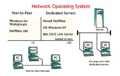
The early versions of Microsoft Windows did not provide any computer networking support. Microsoft added basic networking capability into its operating system starting with Windows 95 and Windows for Workgroups. Microsoft also introduced its Internet Connection Sharing (ICS) feature in Windows 98 Second Edition (Win98 SE). Contrast that with Unix, which was designed from the beginning with networking in view. Nearly any consumer O/S today qualifies as a network operating system due to the popularity of the Internet.

Embedded Operating Systems

A so-called embedded system supports no or limited configuration of its software. Embedded systems like routers, for example, typically include a pre-configured Web server, DHCP server, and some utilities but do not allow the installation of new programs. Examples of embedded operating systems for routers include:

  • Cisco IOS (Internetwork Operating System)
  • DD-WRT
  • Juniper Junos

An embedded OS can also be found inside an increasing number of consumer gadgets including phones (iPhone OS), PDAs (Windows CE), and digital media players (ipodlinux).


You are familiar with the-concept of switching. Circuit switching is the study of data link layer. The services of networks are provided by using the concept of packet switching.

Packet switching can be used as an alternate to circuit switching. In the packet switched networks, data is sent in discrete units that have variable length. They are called as packets. There is a strict upper bound limit on the size of packets in a packet switch network. The packet contains data and various control information. The packet switched networks allow any host to send data to any other host without reserving the circuit. Multiple paths between a pair of sender and receiver may exist in a packet switched network. One path is selected between source and destination. Whenever the sender has data to send, it converts them into packets and forwards them to next computer or router. The router stores this packet till the output line is free.

Then, this packet is transferred to next computer or router (called as hop). This way, it moves to the destination hop by hop. All the packets belonging to a transmission may or may not take the same route. The route of a packet is decided by network layer protocols.

Advantages of packet Switching


  • The main advantage of packet switching is the efficiency of the network. In circuit switching network, a reserved circuit cannot be used by others, till the sender and receiver leave it. Even if no data is being sent on a reserved circuit, no one else can access the circuit. This results in network bandwidth wastage. The packet switching reduces network bandwidth wastage.


  • The other advantage is that the packet switching is more faults tolerant. In case of circuit switching, all the packets are lost if a router in the circuit is down as all the packets follow the same route. But, in case of packet switching network, the packets can be routed over the malfunctioning component of the network. This is because all the packets may follow a different route to the destination.


Advantages of circuit Switching


  • The circuit switching bills the user depending on the distance and duration of connection whereas packet switching network bill users only on the basis of duration of connectivity.

  • The advantage of circuit switching network over packet switching network is that the circuit switching network provides ordered delivery of packets. As all the packets follow the same route. They arrive in correct order at destination.


 Types of Packet Switching

The packet switching has two approaches: Virtual Circuit approach and Datagram approach. WAN, ATM, frame relay and telephone networks use connection oriented virtual circuit approach; whereas internet relies on connectionless datagram based packet switching.

 (i) Virtual Circuit Packet Switching: In virtual circuit packet switching, a single route is chosen between the sender and receiver and all the packets are sent through this route. Every packet contains the virtual circuit number. As in circuit switching, virtual circuit needs call setup before actual transmission can be started. He routing is based on the virtual circuit number.

 (ii) Datagram Packet Switching: In datagram packet switching each packet is transmitted without any regard to other packets. Every packet contain full packet of source and destination. Every packet is treated as individual, independent transmission.

The datagram can arrive at the destination with a different order from the order in which they where sent. The source and destination address are used by the routers to decide the route for packets. Internet use datagram approach at the network layer.


LAN switches rely on packet-switching. The switch establishes a connection between two segments just long enough to send the current packet. Incoming packets (part of an Ethernet frame) are saved to a temporary memory area (buffer); the MAC address contained in the frame's header is read and then compared to a list of addresses maintained in the switch's lookup table. In an Ethernet-based LAN, an Ethernet frame contains a normal packet as the payload of the frame, with a special header that includes the MAC address information for the source and destination of the packet.
Packet-based switches use one of three methods for routing traffic:

  • Cut-through
  • Store-and-forward
  • Fragment-free

Cut-through switches read the MAC address as soon as a packet is detected by the switch. After storing the 6 bytes that make up the address information, they immediately begin sending the packet to the destination node, even as the rest of the packet is coming into the switch.

A switch using store-and-forward will save the entire packet to the buffer and check it for CRC errors or other problems before sending. If the packet has an error, it is discarded. Otherwise, the switch looks up the MAC address and sends the packet on to the destination node. Many switches combine the two methods, using cut-through until a certain error level is reached and then changing over to store-and-forward. Very few switches are strictly cut-through, since this provides no error correction.

A less common method is fragment-free. It works like cut-through except that it stores the first 64 bytes of the packet before sending it on. The reason for this is that most errors, and all collisions, occur during the initial 64 bytes of a packet.

Routers and Switches


You can see that a switch has the potential to radically change the way nodes communicate with each other. But you may be wondering what makes it different from a router. Switches usually work at Layer 2 (Data or Datalink) of the OSI Reference Model, using MAC addresses, while routers work at Layer 3 (Network) with Layer 3 addresses (IP, IPX or Appletalk, depending on which Layer 3 protocols are being used). The algorithm that switches use to decide how to forward packets is different from the algorithms used by routers to forward packets.

One of these differences in the algorithms between switches and routers is how broadcasts are handled. On any network, the concept of a broadcast packet is vital to the operability of a network. Whenever a device needs to send out information but doesn't know who it should send it to, it sends out a broadcast.

For example, every time a new computer or other device comes on to the network, it sends out a broadcast packet to announce its presence. The other nodes (such as a domain server) can add the computer to their browser list (kind of like an address directory) and communicate directly with that computer from that point on. Broadcasts are used any time a device needs to make an announcement to the rest of the network or is unsure of who the recipient of the information should be.

A hub or a switch will pass along any broadcast packets they receive to all the other segments in the broadcast domain, but a router will not. Think about our four-way intersection again: All of the traffic passed through the intersection no matter where it was going. Now imagine that this intersection is at an international border. To pass through the intersection, you must provide the border guard with the specific address that you are going to. If you don't have a specific destination, then the guard will not let you pass. A router works like this. Without the specific address of another device, it will not let the data packet through. This is a good thing for keeping networks separate from each other, but not so good when you want to talk between different parts of the same network. This is where switches come in.

Fully Switched Networks


In a fully switched network, switches replace all the hubs of an Ethernet network with a dedicated segment for every node. These segments connect to a switch, which supports multiple dedicated segments (sometimes in the hundreds). Since the only devices on each segment are the switch and the node, the switch picks up every transmission before it reaches another node. The switch then forwards the frame over the appropriate segment. Since any segment contains only a single node, the frame only reaches the intended recipient. This allows many conversations to occur simultaneously on a switched network.

Switching allows a network to maintain full-duplex Ethernet. Before switching, Ethernet was half-duplex, which means that data could be transmitted in only one direction at a time. In a fully switched network, each node communicates only with the switch, not directly with other nodes. Information can travel from node to switch and from switch to node simultaneously.

Fully switched networks employ either twisted-pair or fiber-optic cabling, both of which use separate conductors for sending and receiving data. In this type of environment, Ethernet nodes can forgo the collision detection process and transmit at will, since they are the only potential devices that can access the medium. In other words, traffic flowing in each direction has a lane to itself. This allows nodes to transmit to the switch as the switch transmits to them -- it's a collision-free environment. Transmitting in both directions can effectively double the apparent speed of the network when two nodes are exchanging information. If the speed of the network is 10 Mbps, then each node can transmit simultaneously at 10 Mbps.

Mixed Networks


Most networks are not fully switched because of the costs incurred in replacing all of the hubs with switches.
Instead, a combination of switches and hubs are used to create an efficient yet cost-effective network.

For example, a company may have hubs connecting the computers in each department and then a switch connecting all of the department-level hubs.

Some of the most common topologies used today include:


  • Bus - Each node is daisy-chained (connected one right after the other) along the same backbone, similar to Christmas lights. Information sent from a node travels along the backbone until it reaches its destination node. Each end of a bus network must be terminated with a resistor to keep the signal that is sent by a node across the network from bouncing back when it reaches the end of the cable.


  • Ring - Like a bus network, rings have the nodes daisy-chained. The difference is that the end of the network comes back around to the first node, creating a complete circuit. In a ring network, each node takes a turn sending and receiving information through the use of a token. The token, along with any data, is sent from the first node to the second node, which extracts the data addressed to it and adds any data it wishes to send. Then, the second node passes the token and data to the third node, and so on until it comes back around to the first node again. Only the node with the token is allowed to send data. All other nodes must wait for the token to come to them.


  • Star - In a star network, each node is connected to a central device called a hub. The hub takes a signal that comes from any node and passes it along to all the other nodes in the network. A hub does not perform any type of filtering or routing of the data. It is simply a junction that joins all the different nodes together.


  • Star bus - Probably the most common network topology in use today, star bus combines elements of the star and bus topologies to create a versatile network environment. Nodes in particular areas are connected to hubs (creating stars), and the hubs are connected together along the network backbone (like a bus network).


 Quite often, stars are nested within stars, as seen in the example below:

The Problem: Traffic

In the most basic type of network found today, nodes are simply connected together using hubs. As a network grows, there are some potential problems with this configuration:


  • Scalability - In a hub network, limited shared bandwidth makes it difficult to accommodate significant growth without sacrificing performance. Applications today need more bandwidth than ever before. Quite often, the entire network must be redesigned periodically to accommodate growth.


  • Latency - This is the amount of time that it takes a packet to get to its destination. Since each node in a hub-based network has to wait for an opportunity to transmit in order to avoid collisions, the latency can increase significantly as you add more nodes. Or, if someone is transmitting a large file across the network, then all of the other nodes have to wait for an opportunity to send their own packets. You have probably seen this before at work -- you try to access a server or the Internet and suddenly everything slows down to a crawl.


  • Network failure - In a typical network, one device on a hub can cause problems for other devices attached to the hub due to incorrect speed settings (100 Mbps on a 10-Mbps hub) or excessive broadcasts. Switches can be configured to limit broadcast levels.


  • Collisions - Ethernet uses a process called CSMA/CD (Carrier Sense Multiple Access with Collision Detection) to communicate across the network. Under CSMA/CD, a node will not send out a packet unless the network is clear of traffic. If two nodes send out packets at the same time, a collision occurs and the packets are lost. Then both nodes wait a random amount of time and retransmit the packets. Any part of the network where there is a possibility that packets from two or more nodes will interfere with each other is considered to be part of the same collision domain. A network with a large number of nodes on the same segment will often have a lot of collisions and therefore a large collision domain.


While hubs provide an easy way to scale up and shorten the distance that the packets must travel to get from one node to another, they do not break up the actual network into discrete segments. That is where switches come in. In the next section, you'll find out how switches assist in directing network traffic.

The Solution: Adding Switches


Think of a hub as a four-way intersection where everyone has to stop. If more than one car reaches the intersection at the same time, they have to wait for their turn to proceed.

Now imagine what this would be like with a dozen or even a hundred roads intersecting at a single point. The amount of waiting and the potential for a collision increases significantly. But wouldn't it be amazing if you could take an exit ramp from any one of those roads to the road of your choosing? That is exactly what a switch does for network traffic. A switch is like a cloverleaf intersection -- each car can take an exit ramp to get to its destination without having to stop and wait for other traffic to go by.

A vital difference between a hub and a switch is that all the nodes connected to a hub share the bandwidth among themselves, while a device connected to a switch port has the full bandwidth all to itself. For example, if 10 nodes are communicating using a hub on a 10-Mbps network, then each node may only get a portion of the 10 Mbps if other nodes on the hub want to communicate as well. But with a switch, each node could possibly communicate at the full 10 Mbps. Think about our road analogy. If all of the traffic is coming to a common intersection, then each car it has to share that intersection with every other car. But a cloverleaf allows all of the traffic to continue at full speed from one road to the next.


Here are some of the fundamental parts of a network:


Network - A network is a group of computers connected together in a way that allows information to be exchanged between the computers.

Node - A node is anything that is connected to the network. While a node is typically a computer, it can also be something like a printer or CD-ROM tower.

Segment - A segment is any portion of a network that is separated, by a switch, bridge or router, from other parts of the network.

Backbone - The backbone is the main cabling of a network that all of the segments connect to. Typically, the backbone is capable of carrying more information than the individual segments. For example, each segment may have a transfer rate of 10 Mbps (megabits per second), while the backbone may operate at 100 Mbps.

Topology - Topology is the way that each node is physically connected to the network (more on this in the next section).

Local Area Network (LAN) - A LAN is a network of computers that are in the same general physical location, usually within a building or a campus. If the computers are far apart (such as across town or in different cities), then a Wide Area Network (WAN) is typically used.

Network Interface Card (NIC) - Every computer (and most other devices) is connected to a network through an NIC. In most desktop computers, this is an Ethernet card (normally 10 or 100 Mbps) that is plugged into a slot on the computer's motherboard.

Media Access Control (MAC) address - This is the physical address of any device -- such as the NIC in a computer -- on the network. The MAC address, which is made up of two equal parts, is 6 bytes long. The first 3 bytes identify the company that made the NIC. The second 3 bytes are the serial number of the NIC itself.

Unicast - A unicast is a transmission from one node addressed specifically to another node.

Multicast - In a multicast, a node sends a packet addressed to a special group address. Devices that are interested in this group register to receive packets addressed to the group. An example might be a Cisco router sending out an update to all of the other Cisco routers.

Broadcast - In a broadcast, a node sends out a packet that is intended for transmission to all other nodes on the network.

Friday 22 March 2013


Wireless LAN vendor Aerohive has added campus Ethernet switching to its product line, and enhanced its HiveManager management platform with new application visibility and context-based policy management. The release signifies the ongoing market trend in unified wired and wireless campus networking.

The new SR series of Aerohive switches will roll out throughout the year. The SR 2024, available now, has 24 front-facing Gigabit Ethernet ports with four additional GbE uplinks. Eight of the ports on the $1,799 switch support 802.1at, or Power over Ethernet Plus (PoE+).


At mid-year, the market will see two more Aerohive switches, the SR2124P and SR2148, with 24 and 48 PoE+ ports of GbE respectively, each with four 10 Gigabit Ethernet uplinks. The SR switches run HiveOS, the same operating system that powers the company's wireless LAN access points. The switches ship with routing protocols and 3G and 4G backup capabilities, which makes them suitable for branch office deployments too.

IASIS Healthcare, a Franklin, Tenn.-based health care company, has deployed the SR2124 as a branch router in several of its remote clinics, said Rodney Dukes, the company's network architect. The company is also considering the Aerohive switches in its campus networks, which are currently all-Cisco. "We're planning to use them in a hospital," Dukes said. "We've got a couple refreshes coming up, and we're looking at putting one in each IDF [Intermediate Distribution Frame]. To manage that switch plus the access points on one platform is awesome."

Aerohive switches: Another step toward a unified wired and wireless LAN

The Aerohive switches highlight the industry's ongoing effort to unify wired and wireless networking so that wireless LANs no longer operate as a separate overlay network, said Andre Kindeness  senior analyst at Cambridge, Mass.-based Forrester Research. Cisco's new Catalyst 3850 wireless control switch was one of the first instances of vendors consolidating the control plane of the network. HP made some recent progress with its 830 Unified Wired-WLAN switch series. Also, the leading pure-play wireless LAN vendor, Aruba Networks, took steps in that direction when it launched its S3500 Mobility Access Switches in 2011.

Network engineers are so busy focusing on hot trends, such as high-performance data center networking and bring your own device initiatives, that they are wary of having two separate management systems for wired and wireless networks, Kindness said. "So, Aerohive is feeling the pressure of finding a way of going into accounts and competing for customers who are liking what Cisco and HP are just starting to deliver on," he said.

Vendors like Aruba and Aerohive might struggle to sell switches into the wiring closets of large networks that are already dominated by Cisco and other incumbent wired-switching vendors, but the branch networking capabilities of Aerohive's SR series could appeal to companies looking to consolidate network services in remote locations, Kindness said. An SR switch can do triple duty as a router, firewall and switch.

A rebuilt HiveManager with application visibility and control

Aerohive also has revamped its management platform, HiveManager, which customers can use on-premises and in the cloud. The company has added Layer 2 to Layer 7 application visibility and control, and has enabled new context-based configuration and policy management capabilities.

HiveManager will now let a network manager set detailed policies. For instance, an enterprise could classify users as VIPs, contractors and employees, then define how each group can interact with a service like YouTube. "The VIP could do anything they want with any application," said Abby Strong, senior product marketing manager at Aerohive. "For a contractor, say, I want to block YouTube. And for other employees, there are some uses for YouTube, but they should not take precedence over business-critical activities, so I'd like to limit it."

Most solutions implement this at a network level by creating different service set identifiers (SSIDs) to enable different optimized experiences based on user identity. "[This is] fine if YouTube is the only application," Strong said. "Do you need to create another SSID if I want to change how they interact with another app? And then there is the complexity of whether you want to base that on what type of device they're using and what their geographic location is. Do you need more SSIDs to customize that experience?"

The new detailed management and policy control in HiveManager has improved how Dukes delivers network services to guest users at IASIS. It's also improved how he manages and troubleshoots the networks for his remote clinics, where users rely on Citrix application virtualization for a lot of services.

"All their applications are Web-based Citrix, so we might have some bandwidth issues or need to apply some Quality of Service," Dukes said. "We're able to see that with the Layer 7 visibility into how those applications are behaving. We have a Riverbed Steelhead at every location, so I can see that maybe we need to give that traffic destined for that application a higher queue to make it work."

The TCP/IP stack is usually installed by default on all Windows 2000/XP/Server products. On earlier versions of Windows, you could add/remove the TCP/IP stack by visiting the network interface card's properties. The Install/Remove option should be available for you.

The good news is that all Linux versions these days have the TCP/IP stack installed by default, so you shouldn't need to do much work, other than configure your network interface cards as required. This of course is a process that differs from one Linux distribution to another.


A quick check to confirm the TCP/IP stack is operating properly, can be done by pinging your machine's loopback interface as shown below:

C:Documents and SettingsAdministrator>ping loopback
Pinging firewall.cx [127.0.0.1] with 32 bytes of data:
Reply from 127.0.0.1: bytes=32 time<1ms TTL=128

Ping statistics for 127.0.0.1:
       
    Packets: Sent = 4, Received = 4, Lost = 0 (0% loss)

Approximate round trip times in milli-seconds:
         
     Minimum = 0ms, Maximum = 0ms, Average = 0ms

If successful, then you know the TCP/IP stack is operating correctly. This works with all Windows and most Linux distributions.
Do you have more questions about networking, VPN security or VoIP?
Then visit Firewall.cx, one of the few websites recommended by Cisco Systems in its world class Cisco Academy program.

Devising a bring-your-own-device (BYOD) security plan would be simple if it merely involved granting network access based on user identity, device or location. But a solid BYOD network security application would consider all of these factors -- and that’s a tall order.

At this point, since there is no proven singular solution, IT shops are instead patching together various tools that range from mobile device management (MDM) to network access control (NAC) and even out-of-band management systems.

Executives at four educational institutions we interviewed for this piece would all like to control hundreds or even thousands of personal devices in an automated way so they aren't burdened by installing software on each client. From there, they’d like to granularly control access depending on a combination of identity and device factors. But each executive is taking a different path to reach that goal.

MDM Tools Are Promising, But Not A Total Solution

All four executives interviewed were already using or evaluating MDM tools. These tools vary by feature depending on the vendor, but generally they track mobile devices on the network and can limit which users get access to specific applications or areas of the network based on company policy.

In general, enterprises are flocking to MDM tools. In 2010-11, 21.2% of companies surveyed by Nemertes Research were using MDM, and the firm predicts this will grow to 84% by the end of 2014, according to analyst Philip Clarke.

Yet MDM alone usually can’t manage users that have multiple devices and attach them all to the wireless LAN (WLAN) using the same identity-based log-in credentials. If the WLAN can’t natively differentiate between vetted and potentially infected devices, the network is at risk.

IT shops must be able to identify multiple devices per user and grant role-based access based on varied user/device pairs. This generally requires integration with other tools, including Identity Management (IDM) and NAC products.

Using Out Of-Band Management For BYOD Security

The Rowan-Salisbury School System in North Carolina needed to control mobile device network access based on a range of variables including device type, location and application, explains Philip Hardin, executive director for technology, at the school system. Yet Hardin’s team needed to support software installations and enforce policies across numerous devices in an automated way.

So the organization implemented a combination of Aerohive’s Hive Manager  an out-of-band network management system, with JAMF Software’s iOS MDM suite.

Aerohive’s Hive Manager lets organizations configure customized policies for each user identity and device type combination. Policies govern network access, firewalling, the time of day that certain access rights are available and tunneling policies for secure VPN access.

“The Hive Manager provides for central data collection and alerts us about rogue clients. It uses device fingerprints to apply specific security based on policy, and monitors device health for individual and collective devices, displaying numerical device health scores visually in a graphical manner,” Hardin says.

Meanwhile, the JAMF Software tests Apple devices to be sure they have the Apple MDM client installed. Then the software directs new devices to a portal to receive device profiles that determine their access rights and privileges. “The integrated solution enables the school to manage application access, [as well as] installation and software updates on devices,” Hardin added. The solution can accomplish profile management and access control without requiring personal devices to hold a NAC client.

Identity Management Central To BYOD Security

Hartwick College, in Oneonta, N.Y., uses an IDM tool alongside next-generation firewalls to handle device management and access.

The Meru Identity Manager controls access for both guest and employee devices through Smart Connect and Guest Connect modules. When a new employee at Hartwick College first attempts to open a Web page, they are redirected to a captive portal page on the Meru IDM appliance.

“Our IDM appliance has a 2048-bit VeriSign certificate, which is used to encrypt the captive portal Web page, which the employee then uses to download SmartConnect as an applet or network profile,” says Davis Conley, executive director of IT at Hartwick College.

SmartConnect configures the device to use the encrypted network, automatically authenticates the user, makes that a preferred network on the device, and then removes the open network from the device’s list of SSIDs, Conley explains.

Guest users, on the other hand, register on the Guest SSID in Guest Connect. Both Smart Connect and Guest Connect have automated role- and policy-based BYOD provisioning. “Guest Connect asks for the user’s real name, phone number and the name of the person on campus they are visiting. ″We can shut them off if there is an issue,” Conley says. Then the Meru IDM uses a mechanism to collect device MAC addresses for future device recognition.

Hartwick College does not, however, use the activity monitoring, policy management and policy enforcement piece of the Meru solution. “We already had policy management in shape. We use Bluecoat packet shaper, a Palo Alto next-generation firewall and a Tipping Point device to see what devices are trading virus-laden content. Then we call in the user to address [the problem],” says Conley.

WLAN Analysis Tools With NAC For BYOD Management

Central Michigan University in Mount Pleasant, Mich. uses Lancope’s StealthWatch network analyzer to monitor behavior on the WLAN and track user activity.

“We use StealthWatch to look for anomalies in behavior and to figure out what the user was trying to do. Then we use a NAC appliance (from Bradford Networks) to identify the user. This is a manual process,” says Ryan Laus, Network Manager, Central Michigan University.

With StealthWatch, Central Michigan University uncovers externally-launched botnet attacks, worms and APTs, as well as internal misuse, policy violations and data leakage, regardless of the device. NetFlow supplies the data that StealthWatch analyzes.

Now the university is testing MDM tools from different providers to enforce policy.

MDM will control what individuals can do on a device using policy, similar to how Active Directory uses group policy controls. It would block unauthorized software installs and enable administrators to set configuration and permission settings for BYOD deployment.

Central Michigan University anticipates using StealthWatch in support of a new MDM package. “If a user figures out how to bypass MDM to install an unapproved application, StealthWatch can look for flows that are out of the policy scope and send an alert to the NAC appliance, which could then move the user/device to a quarantined network,” Laus says.

Integrating IDM With NAC For BYOD Security

The Regional Medical Center at Memphis in Tennessee is using Aruba Networks’ ClearPass integrated mobility management and NAC software to create a self-provisioning system for BYOD.

Users at the medical center will sign in with a standard log-in name and password, and ClearPass will provision based on pre-determined policy. “We won’t have to have them bring their device in and install a security/network profile manually,” says Tony Alphier, Director of IT at The Regional Medical Center at Memphis.

With this process, a NAC controller will prevent devices from getting on the network until they are registered and cleaned.

“[Currently] we are not allowing employees BYOD [internal access] unless they are physicians and bring a laptop. Then we put a profile on their device manually,” says Alphier. “When we add the NAC module from Aruba, we will be able to allow all employees BYOD [access].”

The medical center also uses Aruba’s AirWave to log and monitor device activity and Aruba technology allows Alphier to provide a guest network. “We had Aruba’s Amigopod guest solution. Aruba is combining that with Clear Pass. We can have family and patients and friends access our network and keep our security at the same time,” says Alphier. Guests can self-provision now, receiving a code to connect to the Internet while staying off the internal network.

Wednesday 20 March 2013


Wi-Fi products are used to build WLANs, while WiMAX products are used to build WMANs.
A Wireless Local Area Network (WLAN) is a group of devices linked together by wireless within a relatively small space like a single office building or home. Three WLAN technologies were included in the original 802.11 standard: Infrared, Frequency Hopping Spread Spectrum (FHSS), and Direct Sequence Spread Spectrum (DSSS). 802.11b focused exclusively on DSSS; 802.11a/g/n also used Orthogonal Frequency Division Multiplexing (OFDM).


Wi-Fi is a certification applied to 802.11a/b/g/n products tested by the Wi-Fi Alliance, an industry consortium that promotes interoperability in heterogeneous WLANs. For example, all 802.11g products implement standard OFDM and DSSS, but only Wi-Fi certified products have proven that they correctly support a mandatory subset of features and options.

To create a WLAN, enterprises, small businesses, and home owners can purchase Wi-Fi certified Access Points (APs) and clients (laptops, phones, printers). Clients must be no more than a few hundred feet from the closest AP. Larger buildings can be covered by installing multiple APs that are connected to each other. Most WLANs are deployed indoors, but WLANs can also cover parking lots or courtyards or other local outdoor areas.

Wireless Metropolitan Area Networks (WMANs) use wireless "last mile" technologies to connect subscriber stations (customer premise equipment) to base stations (carrier network infrastructure), providing a wireless alternative to wireline Internet access technologies like DSL, cable, or fiber.

802.16 standards define several WMAN technologies that operate at various frequencies, distances, and speeds to deliver Broadband Wireless Access (BWA). The original 802.16 focused on Fixed BWA, using point to point wireless uplinks to connect subscriber networks to carrier networks and the Internet. More recently, the 802.16e amendment defined Mobile BWA to serve subscriber stations that are not fixed in place, like laptops used in cars and trains.

WiMax is a certification applied to 802.16 products tested by the WiMAX Forum. Carriers build and operate WMANs by purchasing licensed spectrum and then deploying WiMAX base stations throughout a city, region, or other designated coverage area. To use the WMAN, subscribers must purchase wireless services from a carrier. For example, Sprint recently launched a commercial WiMAX service called XOHM in Baltimore. Consumers in and around Baltimore that want to use XOHM must purchase a compatible WiMAX device and pay Sprint for air time.

Here are some key differences between WLANs and WMANs, supported by Wi-Fi and WiMAX products:


  • It's possible to use WMAN technology indoors, but 802.16 protocols are optimized for outdoor operation. It's possible to use WLAN technology outside, but 802.11 protocols were primarily designed for indoor networks.
  • Larger WLANs can be constructed using many densely-spaced Wi-Fi APs, but to blanket miles of territory with wireless, you really want to create a WMAN technology. On the other hand, using WiMAX products for communication between PCs inside the same building would be pricey and impractical -- that's precisely what WLAN technologies were created for.
  • Most office and home WLANs are composed of Wi-Fi products operating in unlicensed spectrum -- channels freely available for use by anyone. WiMAX products most often operate in spectrum licensed to wireless carriers who use them to deliver commercial BWA services.


The bottom line is that WLANs and WMANs are complementary network architectures, supported by standard technologies that were designed for very different environments and purposes. This is why your next laptop may well include both Wi-Fi and Mobile WiMAX adapters. Use the Wi-Fi adapter to connect to your office or home WLAN free-of-charge, but use the WiMAX adapter when you're on the go to reach the Internet through a carrier's WMAN.